Pipe supports
Corrosion at a U-bolt support you cannot unclamp
The clamp is torqued, the line is in service, and the metal under the contact is wasting where no walk-round reaches it.
The support point is where the line goes first
Lines through refineries, chemical plants and offshore platforms rest on structural beam supports and are held with U-bolts. Where an uncoated bolt meets an uncoated pipe, the contact area erodes. Moisture stays in what is left. The manufacturer's sheet calls that support-point corrosion the largest single cause of process pipe failure, ending in pinhole leaks.
None of it is visible from the walkway. The face that corrodes is the one the loop is pressed against, and the water sits in a film the clamp holds there. An inspector reads the top of the pipe and the outside of the bolt. The wall loss is underneath, behind the thing doing the damage.
This site is about parts that close around an asset already in place. This one closes around nothing. It is a tube, and it goes over the shank of the U-bolt before the clamp goes onto the pipe. What earns it a page here is the situation, not the geometry. The line is running, the rack is loaded, and nobody is going to strip a support to paint one contact.
Read the consequence of that before you raise a requisition. A tube needs a free end to go on over. A U-bolt already torqued onto a live line has none. So this is a part for a new support, a replacement bolt, or a shutdown where the clamp is coming off anyway. That reading is this reference's, taken from the shape of the part. The sheet does not spell it out.
It is not rubber, whatever the drawing says
It gets called a rubber sleeve. It is not rubber. The article described here is polyolefin. It is supplied oversize, slid onto the shank, then shrunk down with heat. It holds that recovered shape once it cools. The sheet claims elastomeric behaviour and conformance over irregular contours without splitting. That is where the resemblance comes from.
A moulded rubber liner pushed onto a U-bolt is a different article. This reference holds no selection data for one. If a drawing calls out rubber, say so on the enquiry rather than letting a buyer choose. The two do not swap at the same bolt size.
Heat shrink polyolefin tube for U-bolt coating
A 3:1 polyolefin tube recovered over the shank of a U-bolt to give corrosion and mechanical protection at the bolt-to-pipe contact. Two wall grades over the same diameters: GMWR medium wall and GHWR heavy wall. Technical Qualification Report QR 1025.
- Recovers over the shank without wrinkles, which lowers the risk of cracking the paint film around the pipe as the bolt is torqued down
- Hard and durable enough to protect the pipe paint, without setting up a capillary crevice around the circumference of the pipe
- Jacket tear resistance and elastomeric behaviour, conforming over irregular contours without splitting
- Impact and abrasion resistance where a tube rubs against sharp objects or sits in constant friction
- Strain relief at the clamp
- One code covers a band of shank diameters, which cuts the number of sizes a store has to carry
- Claimed unaffected by heat, ultraviolet rays, vibration and sandblasting
| Fitted to | The shank of the U-bolt, before the clamp goes on the pipe |
|---|---|
| Shrink ratio | 3:1 |
| Medium wall range | GMWR 9/3 to GMWR 50/16, wall 1.5 mm to 3.0 mm |
| Heavy wall range | GHWR 12/3 to GHWR 50/16, wall 2.4 mm to 4.0 mm |
| Recovered internal diameter | 3 mm to 16 mm across both ranges |
| Continuous temperature limit | −40 °C to +110 °C |
| Dielectric strength | 12 kV/mm minimum |
| Qualification report | QR 1025 |
| Compliance stated on the sheet | RoHS and REACH |
| Market segment | Electrical, offshore, marine, industrial oil and gas utilities |
Reading the two diameter columns
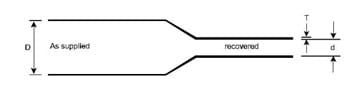
Every row carries three numbers. D min is the internal diameter as supplied. d max is the internal diameter once the tube has fully recovered. T is the recovered wall, held to plus or minus 10 percent.
Size from the two diameters, in that order. The shank has to pass through D min or the tube will not go on. It then has to sit above d max, or the tube reaches its recovered size before it has gripped anything.
The headline ratio is 3 to 1. The chart does not hold to it. Nine of the twelve GMWR rows work out above 3 to 1 on their own two figures, and GHWR 12/3 is 4 to 1. Order against the diameters, never against the ratio.
GMWR medium wall selection chart
| Code | D min. (mm) | d max. (mm) | T ±10% (mm) |
|---|---|---|---|
| GMWR 9/3 | 9 | 3 | 1.5 |
| GMWR 10/3 | 10 | 3 | 1.5 |
| GMWR 12/4 | 12 | 4 | 1.65 |
| GMWR 16/5 | 16 | 5 | 2.0 |
| GMWR 19/6 | 19 | 6 | 2.0 |
| GMWR 22/6 | 22 | 6 | 2.0 |
| GMWR 27/8 | 27 | 8 | 2.75 |
| GMWR 30/8 | 30 | 8 | 3.0 |
| GMWR 33/10 | 33 | 10 | 3.0 |
| GMWR 35/12 | 35 | 12 | 2.5 |
| GMWR 40/12 | 40 | 12 | 3.0 |
| GMWR 50/16 | 50 | 16 | 3.0 |
D and d are internal diameters; T is wall thickness. From the U-bolt coating sheet, Technical Qualification Report QR 1025.
GHWR heavy wall selection chart
| Code | D min. (mm) | d max. (mm) | T ±10% (mm) |
|---|---|---|---|
| GHWR 12/3 | 12 | 3 | 2.4 |
| GHWR 19/6 | 19 | 6 | 2.5 |
| GHWR 22/6 | 22 | 6 | 2.75 |
| GHWR 27/8 | 27 | 8 | 3.5 |
| GHWR 30/8 | 30 | 8 | 3.5 |
| GHWR 33/10 | 33 | 10 | 3.5 |
| GHWR 35/12 | 35 | 12 | 3.5 |
| GHWR 40/12 | 40 | 12 | 4.0 |
| GHWR 50/16 | 50 | 16 | 4.0 |
Same diameters, thicker wall, and three fewer sizes. GHWR starts at 12 mm, so the 9 mm and 10 mm bolts have no heavy wall option.
Material properties, as supplied and after ageing
| Property | Value | Standard |
|---|---|---|
| Tensile strength | 12 N/mm² minimum | ASTM D638 |
| Ultimate elongation | 350% minimum | ASTM D638 |
| Longitudinal change | −10% maximum | ASTM D2671 |
| Water absorption | 0.5% maximum | ASTM D570 |
| Ageing conditioning | 120 °C for 500 hours | ASTM D2671 |
| Tensile strength after ageing | 12 N/mm² minimum | ASTM D638 |
| Ultimate elongation after ageing | 300% minimum | ASTM D638 |
Thermal and electrical limits
| Property | Value | Standard |
|---|---|---|
| Heat shock, 250 °C for 30 minutes | No cracking or flowing | ESI 09-11 |
| Continuous temperature limit | −40 °C to +110 °C | IEC 216 |
| Dielectric strength | 12 kV/mm minimum | ASTM D149 |
| Volume resistivity | 1 × 10¹³ Ω·cm minimum | ASTM D257 |
| Dielectric constant | 5 maximum | ASTM D150 |
Heat shock is a 30 minute excursion, not a service rating. The number that governs where the clamp lives is the continuous limit.
The code on its own will not order the right tube
Five revisions of this datasheet are in circulation and they do not agree. The current one publishes the two charts above under QR 1025. Two earlier revisions carry a shorter medium wall list with different walls at the same code. GMWR 12/4 is 1.8 mm there against 1.65 here. GMWR 22/6 is 2.3 against 2.0. GMWR 50/16 is 2.7 against 3.0. Those revisions also list a GMWR 16/6 where the current sheet has 16/5. One of the two prints that identical table under the prefix GRMW. A fourth revision uses GUMW and lists three sizes only. It raises tensile strength to 14 N/mm² and dielectric strength to 15 kV/mm. Across the whole set the continuous limit moves between −40 °C and −55 °C, and volume resistivity between 1 × 10¹³ and 1 × 10¹⁴ Ω·cm. There is a second collision on top of that. GMWR and GHWR are also the codes of the general co-extruded medium wall and heavy wall tubing, qualified under QR 1014. That series runs to 200/64 and its sizes are near neighbours rather than matches: GHWR 19/7 against 19/6 here, GHWR 30/9 against 30/8, GMWR 50/17 against 50/16. Quote the full code, the wall, and the qualification report you were issued against. GMWR 50/16 is not one part.
Not on this sheet — ask before you specify
The U-bolt sheet publishes no flammability rating and no colour. It gives no recovery or shrink temperature, no adhesive lining, and no salt-spray or coastal exposure result. It names no cable or tubing product standard it conforms to. It also carries no hardness row, in spite of the prose arguing that the material has the right hardness to protect pipe paint. Several of those figures do exist on the general co-extruded GMWR and GHWR sheet. That one gives a shrink temperature of 125 °C, a hardness of 45 ±10 Shore D, standard colour black, an optional hot melt adhesive lining, and conformance to IEC 60684-3-247. Do not carry them across. It is a different qualification report over a different size set. The two sheets already disagree on ageing conditioning: 120 °C for 500 hours here, 150 °C for 168 hours there. If your specification needs any of it, ask the manufacturer to confirm against QR 1025 in writing.
Four conditions the sheet says it is unaffected by
- Heat
- A rack in the sun and a hot line inside the clamp. The continuous band is −40 °C to +110 °C, by IEC 216. Heat shock at 250 °C for 30 minutes leaves no cracking or flowing, by ESI 09-11. Only the first of those two is a service figure.
- Ultraviolet
- A pipe rack is outdoors for the life of the plant, and the coating on a clamp is not repainted with the steelwork around it. UV resistance is asserted in the features list. No exposure hours and no weathering method sit behind it.
- Vibration
- Pump and compressor discharge lines work a clamp against the pipe all shift. The sheet's own words are constant friction and rubbing against sharp objects. Abrasion resistance is claimed with no abrasion figure printed.
- Sandblasting
- Racks are blasted and repainted at turnaround. The claim is that grit stripping the paint either side of the clamp does not take the tube with it. No blast medium, nozzle pressure or standoff distance is stated, so agree the blast spec with the contractor first.
Where this is the wrong part
Any one of these and the tube is not the answer. Written so a supervisor can sign against the line rather than argue it.
- It protects the contact, not the pipe. Wall loss already under a clamp is an inspection question. Coat over it and you have hidden the evidence somebody needs.
- There is no free end. A U-bolt torqued onto a running line cannot be threaded, so this belongs to a new support, a replacement bolt or a planned shutdown.
- The shank falls outside the charts. Recovered internal diameters run 3 mm to 16 mm on both ranges and stop there.
- Service is above +110 °C or below −40 °C continuous. Steam and hot process lines sit past the top of that band.
- What actually needs coating is the pipe. A weld joint on a coated line is a wraparound job and a different article: see the three-layer pipeline sleeve.
- Somebody wants an electrical rating out of it. 12 kV/mm is a property of the polyolefin per millimetre of wall, not a voltage class for a pipe clamp.
- The specification demands a flame rating or a named colour. Neither is printed on this sheet.
- The line is lagged and the clamp bears on the insulation or a shoe. Nothing on this sheet addresses that case.
Where to go next
- Pole protection sleeveThe other asset that rots at a contact nobody opens, this time at the ground line.
- Three-layer pipeline sleeveFor when the problem is the pipe wall and the field weld rather than the clamp.
- Wraparound or tubularThe access question that decides whether a tube is available to you at all.
- Reading a heat shrink datasheetWhat ASTM D638, ASTM D2671, ASTM D149, ASTM D257 and ESI 09-11 actually measure.
- U-bolt coating on the manufacturer's siteGala Thermo Shrink Pvt. Ltd. of Mumbai manufacture the tube. Their page carries the application list and the QR 1025 reference quoted above.
Send the shank diameter, not the pipe size
Measure across the thread of the U-bolt in millimetres and count the supports. Say what the line runs at, and whether the rack is coastal. Say whether the bolts are new, being replaced, or coming off at a shutdown. Those five things settle the code and the wall grade in one reply.