Post-tensioning duct
Sealing a post-tensioning duct joint before the grout goes in
The seam between two duct lengths is the one nobody can open again.
A leak at the seam is found after the deck is poured
Two duct lengths meet on the cage. The connection is taped, or pushed together, or left as it was delivered. Then the strand goes in, the concrete goes round it, and the duct is inside the structure. That seam is now unreachable for the life of the deck.
An unsealed connection leaks in both directions. Grout pumped along the duct escapes at the seam, and every millilitre that escapes leaves a void behind it. Site water and groundwater enter through the same gap. Neither is visible while it is happening. Both are found after the tendon is stressed and the pour has gone off, which is the point at which the answer stops being cheap.
The coupler closes that seam before any of it starts. It is a cross-linked polyolefin tube lined with hot-melt adhesive. Heat recovers it onto both duct lengths in one pass and the lining seals to IP68. The manufacturer's claim for the backing is conformance over irregular contours, which on a ribbed duct means the recovery has to follow the corrugation rather than bridge it.
Read the geometry before you read the chart. This is tubing, closed all the way round. It is not a wraparound with a rail you shut by hand. It has to be threaded onto one duct length before the two are brought together, and no sheet publishes a method for fitting it to a connection that is already made up. Get it into the sequence at assembly or you do not get it at all.
GMW heat shrink coupler for post-tensioning duct joints
A closed tube of cross-linked polyolefin, lined with hot-melt adhesive, recovered over the connection between two consecutive lengths of post-tensioning duct. Seventeen codes run from GMW 70/22 to GMW 863/250, and the post-tensioning sheet supplies every one of them at 300 mm long.
- Recovers onto both duct lengths at once, with no closure to align and no channel to feed
- 3:1 recovery lets one code cover a span of duct diameters, so fewer sizes sit in the store
- Rated by the manufacturer for wet and dry underground conditions
- No cracking after 4 hours at −40 °C, and no cracking or flowing after 30 minutes at 250 °C
- Longitudinal change held to −10 percent maximum, which is 30 mm on a 300 mm piece; set your cover either side of the seam with that figure in hand
- Customised dimensions, length and colour are offered against order
| Substrate | The connection between two consecutive lengths of post-tensioning duct |
|---|---|
| Codes | GMW 70/22 to GMW 863/250, seventeen sizes |
| Internal diameter as supplied, D min | 70 mm to 863 mm |
| Internal diameter after recovery, d max | 22 mm to 250 mm |
| Shrink ratio | 3:1 |
| Recovered wall, T | 2.7 mm to 3.5 mm, tolerance ±10 percent |
| Length per piece | 300 mm on every code |
| Backing | Cross-linked polyolefin |
| Lining | Hot melt, sealing to IP68 |
| Shrink temperature | 125 °C |
| Continuous temperature limit | −40 °C to +110 °C |
Selection chart
| Code | D min (mm) | d max (mm) | T ±10% (mm) | Length per piece (mm) |
|---|---|---|---|---|
| GMW 70/22 | 70 | 22 | 2.7 | 300 |
| GMW 90/28 | 90 | 28 | 3.0 | 300 |
| GMW 105/30 | 105 | 30 | 3.0 | 300 |
| GMW 115/34 | 115 | 34 | 3.2 | 300 |
| GMW 130/36 | 130 | 36 | 3.2 | 300 |
| GMW 140/42 | 140 | 42 | 3.2 | 300 |
| GMW 160/50 | 160 | 50 | 3.3 | 300 |
| GMW 180/55 | 180 | 55 | 3.3 | 300 |
| GMW 200/60 | 200 | 60 | 3.5 | 300 |
| GMW 250/70 | 250 | 70 | 3.5 | 300 |
| GMW 320/90 | 320 | 90 | 3.5 | 300 |
| GMW 375/110 | 375 | 110 | 3.5 | 300 |
| GMW 425/125 | 425 | 125 | 3.5 | 300 |
| GMW 550/157 | 550 | 157 | 3.5 | 300 |
| GMW 680/200 | 680 | 200 | 3.5 | 300 |
| GMW 760/215 | 760 | 215 | 3.5 | 300 |
| GMW 863/250 | 863 | 250 | 3.5 | 300 |
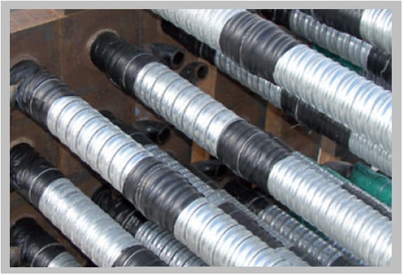
From the post-tensioning duct joint sheet, Issue 2, July 2024. D min is the bore as supplied and d max is the bore after full recovery, so the duct outside diameter at the seam has to fall between the two. The sheet prints no duct-diameter column, so that reading is arithmetic on its own chart and not a published figure. Watch the prefix as well: the couplers in the manufacturer's photograph above are printed GCMW 140/42 and GCMW 70/22, while the chart calls the same two sizes GMW 140/42 and GMW 70/22. Quote the numbers and confirm the prefix on the order.
Physical properties
| Property | Value | Test method |
|---|---|---|
| Tensile strength | 12 N/mm² min. | ASTM D638 |
| Ultimate elongation | 350 % min. | ASTM D638 |
| Longitudinal change | −10 % max. | ASTM D2671 |
| Hardness | 45 ±10 Shore D | ASTM D2240 |
| Water absorption | 0.5 % max. | ASTM D570 |
Tensile strength is the one figure on this sheet that is not stable across issues. Read the warning below before it goes into a specification.
Two datasheets, both marked Issue 2, disagree on tensile strength
The sheet linked above is stamped Issue 2, July 2024, and gives tensile strength as 12 N/mm² and 10 N/mm² after ageing. Another one-page sheet for the same coupler is stamped Issue 2, June 2024, and gives 20 N/mm² and 14 N/mm². The manufacturer's own product page still carries the higher pair. Elongation, longitudinal change, hardness, water absorption and every thermal and electrical value are identical across both, so this is a revision to one property rather than a different product, and the direction is downward. Neither sheet carries a revision number that separates them. Ask your supplier which issue date they are quoting against, in writing, before either tensile figure reaches a specification.
Thermal properties
| Property | Value | Test method |
|---|---|---|
| Accelerated ageing | 120 °C for 500 hrs. | ASTM D2671 |
| Tensile strength after ageing | 10 N/mm² min. | ASTM D638 |
| Ultimate elongation after ageing | 300 % min. | ASTM D638 |
| Low temperature flexibility, −40 °C for 4 hrs. | No cracking | ASTM D2671 |
| Heat shock, 250 °C for 30 min. | No cracking or flowing | ESI 09-11 |
| Shrink temperature | 125 °C | IEC 216 |
| Continuous temperature limit | −40 °C to +110 °C | IEC 216 |
Electrical properties
| Property | Value | Test method |
|---|---|---|
| Dielectric strength | 12 kV/mm min. | ASTM D149 |
| Volume resistivity | 1 × 10¹⁴ Ohm.cm min. | ASTM D257 |
| Dielectric constant | 5 max. | ASTM D150 |
These are material properties of the polyolefin wall. A duct is not an insulator and none of these figures gives the finished joint a voltage class.
Where this is the wrong part
Settle each of these at the bill of materials stage. Every one of them is cheaper to answer before the cage is tied.
- It seals. It does not carry. The tendon and the structure take the load. Nothing in the recovered wall is structural and no load figure is published for the joint it makes.
- It is not a tendon protection system on its own. It closes one seam in that system. The grout, the anchorages and the duct itself do the rest, and this sheet says nothing about any of them.
- The joint is already made up. A closed tube cannot be fitted around a connection after the two lengths are together. Order it into the assembly sequence, not into a remedial one.
- The duct is outside the chart. Recovery stops at 22 mm bore on the smallest code and the largest supplied bore is 863 mm. Outside those, there is no published GMW size.
- You need a pressure figure. IP68 is an ingress classification. The sheet publishes no grout pressure, no vacuum rating and no burst figure for the finished joint.
- No flame is allowed at the working position. Recovery is a heat operation at 125 °C and the sheet publishes no flame-free method.
- The pipe is pre-insulated and you are closing an end, not a joint. That is a pre-insulated pipe sealing cap, a different part with a different chart.
- The duct is corrugated HDPE on a water, sewer or cable run. The codes look identical and the published piece lengths are not. That job is covered on district heating and pipe jointing.
Not published — ask the manufacturer
Four things a post-tensioning specification usually wants are absent from both issues of this sheet. There is no duct outside-diameter column, so size selection is inferred from D and d. There is no adhesion or peel figure, and none to galvanised steel strip duct or to HDPE duct separately. There is no time or temperature guidance for recovery beyond the 125 °C shrink point. And there is no statement on chloride content or on compatibility with cementitious grout. Put all four in the enquiry rather than reading them off the table.
Wet trench, dry yard, and what the no-special-skill line actually covers
The sheet's first benefit line says installation needs no special skill. That claim rests on three things, and it is worth knowing which three. Recovery is 3:1, so a code chosen slightly large still closes down onto the duct. The tube is closed, so nothing has to be aligned, zipped or patched. The lining is hot melt, so it flows before it sets and fills the corrugation profile instead of having to be laid into it.
What the claim does not cover is the heat. It is applied by hand, and 125 °C is a shrink point, not a torch setting. No dwell time, torch distance or recovery check is published on this sheet. Prepare the bond faces as you would for any hot melt: installing a heat shrink sleeve sets that out once, for every product here.
Four resistances are claimed, and each maps to a condition a post-tensioning site produces. Heat is the duct sitting on an open deck through a summer day, against a continuous limit of −40 °C to +110 °C. Ultraviolet is the same duct waiting weeks between assembly and pour. Vibration is the poker driven into wet concrete a hand's width away. Sand-blasting and abrasion are the grit and dropped steel of a rebar cage being tied around it.
Wet and dry underground service is rated. That covers the duct in the ground. It says nothing about a wet bond face at the moment of recovery, and hot melt seals what it can wet out.
Where to go next
This page holds the coupler and nothing else. The neighbouring decisions are held elsewhere on this site.
- District heating and pipe jointingThe joint sequence in order, and the same GMW codes used to joint corrugated HDPE
- Pre-insulated pipe sealing capGPPC single and double outlet, for closing an end rather than a seam
- Wraparound or tubularOne question that decides whether a closed tube was ever an option on this job
- Installing a heat shrink sleeveSurface preparation, torch passes and the indicator paint
- Reading the test methodsWhat ASTM D2671, ESI 09-11 and IEC 216 measure, in one table
- Why wraparound repairs failHow a sealed joint comes apart later, diagnosed rather than described
Getting a usable quotation on the first email
Send the duct outside diameter at the seam, the duct type and wall form, the number of joints, the site condition the ducts wait in before the pour, and the issue date of any datasheet already written into your specification. The coupler is manufactured by Gala Thermo Shrink Pvt. Ltd. at Palghar and Surat SEZ, India; this site indexes and explains the range and does not make it.