Pipeline field joint
Three-layer sleeve wrapped on a weld joint already in the trench
The joint is coated last, in the worst conditions, by the crew that has been out there longest.
The one band of steel the coating plant never touches
A coated line leaves the mill under factory control. Every metre of it, except the ends. Those ends are cut back so they can be welded, and the weld is made in the field. It is then radiographed, and only after that is it coated. That coating goes on in a trench, in wind or heat, at the end of a shift. The cutback is the one place on a buried line where soil, water and cathodic-protection current reach bare steel.
GTWS is the part that closes that band. It is a sleeve of cross-linked polyethylene with a hot-melt adhesive on the inside face. You do not thread it over a pipe end. You wrap it around a joint that is already welded and, on most jobs, already lowered.
The adhesive has to bond to two unlike surfaces in the same wrap. It bonds to the bare steel across the cutback, and to the pipe's own polyethylene coating on both sides of it. That is what makes the finished joint continuous rather than patched. The recovered sleeve then resists liquid pressure, bacteria, mildew, cathodic-protection current and chemical attack from liquids and solvents, and it stops the coat separation that ultraviolet light causes on an exposed run.
If the pipe end is still free, you have no reason to accept a seam at all. Settle the part type before you settle the size: wraparound or tubular.
GTWS three-layer corrosion protection sleeve
A wraparound sleeve for the weld joints of buried or exposed steel pipeline and of insulated pipeline. Cross-linked polyethylene backing, hot-melt adhesive lining, supplied with a separate closure patch. Ordered against pipeline outer diameter from 159 mm to 1016 mm, always at 500 mm width.
- Bonds across the cutback to bare steel and to the mainline PE coating either side of it
- Peel strength published at 25 °C and again at 50 °C, so the hot figure is visible before you order
- Retained elongation of 100 percent after 24 hours in 10 percent HCl
- Tensile strength still 21 N/mm² after 150 °C for 504 hours, against 22 N/mm² unaged
- No cracking after 4 hours at −15 °C
- Impact resistance above 15 J and abrasion loss of 30 mg, both relevant to backfill damage
| Substrate | Weld joints on buried or exposed steel pipeline, and joints on insulated pipeline |
|---|---|
| Pipeline OD range | 159 mm to 1016 mm |
| Sleeve width | 500 mm, on every size |
| Flat sleeve length | 620 mm at 159 mm OD, rising to 3430 mm at 1016 mm OD |
| Closure | Separate patch, 500 mm wide, 100 mm to 200 mm long by size |
| Backing | Cross-linked polyethylene |
| Adhesive | Hot melt, softening point 95 °C |
| Cathodic disbondment | 3 rad |
| Highest published peel | 120 N/cm to FBE at 25 °C |
Order it against outer diameter, and check the overlap yourself
GTWS is selected on the pipeline outer diameter, not on a nominal bore. Measure the coated OD at the cutback before you raise the requisition. Fifteen codes cover 159 mm to 1016 mm and all of them are 500 mm wide, so the sleeve covers a 500 mm band across the joint whatever the diameter.
What changes with diameter is the flat length. It runs 620 mm at 159 mm OD and 3430 mm at 1016 mm OD. Take the smallest size: the circumference of a 159 mm pipe is close to 500 mm, and the flat sleeve is 620 mm, so roughly 120 mm of it is overlap. The manufacturer does not print an overlap figure anywhere. That number is arithmetic on its own chart, and you should do the same sum for your size before the crew does it with a tape in the trench.
The closure patch grows too, from 100 mm long on the smallest code to 200 mm on the largest, at a constant 500 mm width. Every intermediate code, with its sleeve length and its patch length, is on the pipeline sleeve size chart.
Sleeve and closure patch, mechanical
| Property | Value | Standard |
|---|---|---|
| Tensile strength | 22 N/mm² | ASTM D638 |
| Ultimate elongation | 550% | ASTM D638 |
| Impact resistance | greater than 15 J | ASTM G14 |
| Hardness | 50 ±5 Shore D | ASTM D2240 |
| Water absorption | 0.5% | ASTM D570 |
| Abrasion resistance | 30 mg | ASTM D1044 |
| Cathodic disbondment | 3 rad | ISO 21809-3 |
Cathodic disbondment is the figure a pipeline buyer reads first, and 3 rad means nothing until you know how the test is run. That is set out on cathodic disbondment.
After ageing, and at low temperature
| Property | Value | Standard |
|---|---|---|
| Thermal ageing conditioning | 150 °C for 504 hours | ASTM D2671 |
| Tensile strength after ageing | 21 N/mm² | ASTM D638 |
| Ultimate elongation after ageing | 575% | ASTM D638 |
| Low-temperature flexibility, −15 °C for 4 hours | No cracking | ASTM D2671 |
Elongation reads higher after ageing than before it, 575% against 550%. Treat that as one sample set, not as a trend.
Hot-melt adhesive peel strength
| Bond | Peel at 25 °C | Peel at 50 °C |
|---|---|---|
| Sleeve PE to bare steel | 100 N/cm | 30 N/cm |
| Sleeve PE to FBE, fusion-bonded epoxy | 120 N/cm | 35 N/cm |
| Sleeve PE to the pipe's PE coating | 110 N/cm | 30 N/cm |
The method is ASTM D2671. This pair of columns is the most-skipped thing on the sheet. Every bond loses about two thirds of its peel between 25 °C and 50 °C, and a buried line in an Indian summer, or any line carrying warm product, sits nearer the second column than the first. Specify against the hot figure.
Chemical resistance, 24 hours immersion
| Immersion | Retained elongation |
|---|---|
| 10% HCl | 100% |
| 10% NaOH | 97% |
| 10% NaCl | 98% |
The method is ASTM D2671. These are 24-hour figures. They tell you the sleeve survives a soil chemistry excursion; they are not a service life in a contaminated backfill.
Electrical
| Property | Value | Standard |
|---|---|---|
| Dielectric strength | 36 MV/m | ASTM D149 |
| Volume resistivity | 1 × 10¹³ Ω·cm | ASTM D257 |
These two matter on a cathodically protected line, where the coating has to stay resistive enough that the current goes to defects rather than through the sleeve. What each test method actually measures is on test standards.
What is not published for GTWS
There is no standalone GTWS datasheet in the manufacturer's published PDF library. Every figure above is transcribed from the manufacturer's product page for the three-layer sleeve. Four numbers a specifier needs are absent from it. Recovered wall thickness. Shrink ratio. Maximum continuous service temperature of the recovered sleeve. Preheat temperature at the steel before the sleeve is applied. Ask for all four in writing before GTWS goes into a coating specification, because a field joint procedure that omits preheat is the procedure that fails.
Where this is the wrong part
Six situations where GTWS is the wrong thing to raise. Read these before you take the numbers above as a specification.
- It protects the field weld joint. It is not a mainline coating, and wrapping 500 mm bands along a run of failed coating is not a rehabilitation.
- It is sized to outer diameter. Below 159 mm and above 1016 mm OD there is no published GTWS code, so a 114 mm flowline is outside the range.
- It carries no pressure rating and no wall-loss rating. It is a coating, not a structural repair clamp, and it restores no metal.
- It is not a cable product. For a damaged LV or MV jacket use the wraparound cable repair sleeve.
- It does not seal a pre-insulated casing where a service pipe leaves it. That is a pre-insulated pipe sealing cap.
- It will not rescue a joint prepared badly. Peel is quoted on blast-cleaned steel and on sound PE, and neither figure survives grease, mill scale or a cold substrate.
Two constituents are named. The third is not.
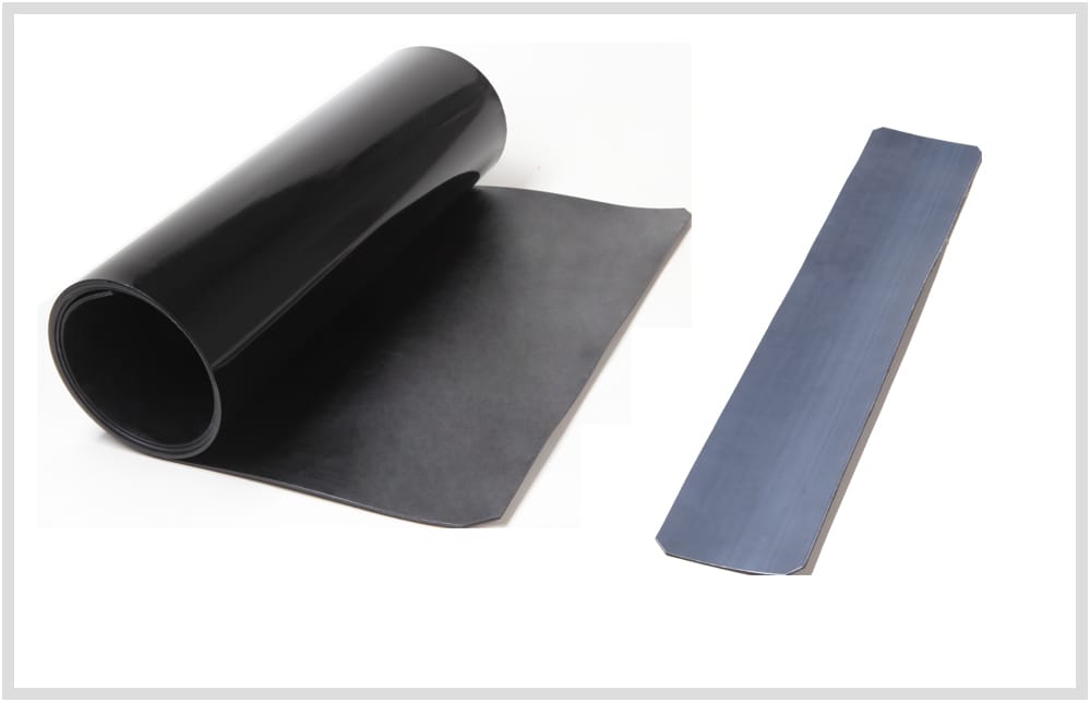
The photograph shows the sleeve before recovery, with its closure patch alongside. The glossy face goes outward. The matt face is the adhesive, and it is the only part of the assembly doing corrosion work.
The manufacturer names two constituents in print: cross-linked polyethylene and a hot-melt adhesive with a 95 °C softening point. It calls the product three-layer and does not name the third anywhere on its page. Do not assume the sleeve is a complete field joint system on its own. Ask what goes on the blast-cleaned steel first, and get that answer inside the coating procedure rather than in an email.
The overlap is a PE-to-PE bond, and the table above gives that bond 110 N/cm at 25 °C and 30 N/cm at 50 °C. At 50 °C the overlap and the steel bond both sit at 30 N/cm, the lowest pair on the sheet. So the seam is never stronger than the joint's weakest interface, and it is the one interface an inspector can see. Where the patch lands on the clock face is a decision, not a detail, and it belongs to the installation sequence.
Next, in the order a pipeline job needs them
- Pipeline sleeve size chart, 159 to 1016 mmEvery GTWS code with its flat sleeve length and its closure patch length.
- Cathodic disbondment, and why it is the field joint's pass or failWhat 3 rad is measured against, and what the number does not cover.
- How to install a wraparound heat shrink sleevePreparation, patch placement and recovery, in sequence.
- Why wraparound sleeve repairs fail in the groundDiagnosis after the fact, for a joint already backfilled.
- Reading a heat shrink datasheet without taking it on trustASTM D2671, ASTM G14 and ASTM D1044, and what each one actually proves.
- Sealing joints on a district heating network already welded inThe adjacent problem, on insulated pipe rather than coated steel.
Send the coated OD, the mainline coating type and the operating temperature
Those three lines are what turn a quotation round in one email. Pipeline outer diameter measured over the coating, whether the mainline is FBE or PE, the highest metal temperature the joint will see in service, and the number of joints. Quote the hot peel column back at whoever answers, and see whether they engage with it.