Pipe systems
Pre-insulated pipe sealing cap, single and double outlet
The insulation stops short of the weld. Water is into it long before the trench is backfilled.
A pre-insulated pipe is finished everywhere except at its two ends.
The outer casing and the insulation beneath it both stop short. Bare service pipe runs on past them, because that stub is where the field weld has to be made. Until something closes over it, the insulation is open at both ends of every length delivered.
The manufacturer states the job of this part in one line. It prevents water access to the exposed insulation at the weld joint area.
Nothing about that failure announces itself. No pressure drops, no alarm sounds, no wet patch shows at grade. The network keeps delivering, at a heat loss nobody designed for, until somebody asks why the operating cost has moved.
By then the wet lengths have to be found and dug up. That is what the cap is bought against.
The part is a moulded cap in cross-linked polyolefin, lined with hot-melt adhesive or mastic. It recovers over the casing at the wide end and down onto the service pipe at the narrow end. GPPC1 has one outlet. GPPC2 has two, for a casing carrying two service pipes.
GPPC1 and GPPC2 pre-insulated pipe sealing cap
A cross-linked polyolefin heat shrink cap, lined with hot-melt adhesive or mastic, recovered over the casing end of a pre-insulated pipe and down onto the service pipe. Manufactured by Gala Thermo Shrink Pvt. Ltd.
- Watertight against weathering, moisture and contamination, rated IP 68
- Resistant to UV rays and ozone
- Seven of the twenty-four single-outlet sizes are footnoted as tooling developed on demand
- Mastic length does not vary with size: 30 mm on the body and 15 mm on each outlet, on every row of both charts
| Material | Cross-linked polyolefin |
|---|---|
| Lining | Hot-melt adhesive or mastic |
| Environmental seal | IP 68 |
| Single outlet codes | GPPC1-1030 to GPPC1-225300, 24 published sizes |
| Double outlet codes | GPPC2 1565S to GPPC2 55175AA, 10 published sizes |
| Body diameter, GPPC1 | 60 to 570 mm as supplied, recovering to 30 to 300 mm |
| Body diameter, GPPC2 | 115 to 355 mm as supplied, recovering to 65 to 180 mm |
| Recovered wall, body | 2.2 mm to 3.7 mm, tolerance ±10% |
| Recovered wall, outlet | 2.0 mm to 4.5 mm, tolerance ±10% |
| Mastic length | 30 mm minimum on the body, 15 mm minimum on each outlet |
| Continuous temperature limit | -40 °C to +100 °C |
| Fitting | Can be factory installed before despatch |
Read the drawing before you read the chart
D is the internal diameter of the wide body, which goes over the casing. Lower-case d is the outlet, which goes over the service pipe. Tb is the wall on the body, Tc the wall on the outlet, L the body length and l the outlet length. The arrow marked Adhesive lining points at the inner face of both.
The chart then hangs a suffix on each letter. An s means as supplied. An f means after free recovery, which is what the part reaches shrunk with nothing inside it.
That is why Ds is printed as a minimum and Df as a maximum. They are the two ends of one band: the casing must be small enough to enter the cap as supplied, and large enough that the cap is still trying to shrink when it meets it. Neither sheet prints that rule in words, so on a diameter close to either end of a band, confirm it before the order goes in.
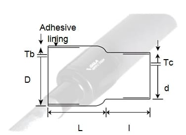
The dimension letters, as printed
- D, d
- Internal diameter. Capital D is the body that goes over the casing; lower-case d is the outlet that goes over the service pipe.
- s
- As supplied. Ds and ds are the internal diameters before any heat is applied, and both are printed as minimums.
- f
- After free recovery. Df, df, Lf and lf are what the part reaches shrunk with nothing inside it. The diameters here are printed as maximums.
- L, l
- Length. Capital L is the body, lower-case l is the outlet.
- Tb, Tc
- Wall thickness after free recovery. Tb on the body, Tc on the outlet. Both carry a ±10% tolerance, so a 2.3 mm wall is 2.07 mm at the bottom of tolerance.
- Mlb, Mlc
- Mastic length of body and mastic length of finger. Both are minimums and neither moves with size: 30 mm and 15 mm on every published code.
- AL
- Adhesive length. The legend on the double-outlet sheet defines it and no column in either chart reports it. Ask for it by name if a specification has to call it out.
Single outlet selection chart, GPPC1
| Code | Ds | Df | ds | df | Ls | Lf | ls | lf | Tb ±10% | Tc ±10% |
|---|---|---|---|---|---|---|---|---|---|---|
| GPPC1-1030 | 60 | 30 | 45 | 10 | 70 | 70 | 40 | 50 | 3.2 | 4.5 |
| GPPC1-1047* | 110 | 47 | 34 | 10 | 65 | 40 | 30 | 75 | 2.5 | 2.5 |
| GPPC1-1575* | 150 | 75 | 34 | 15 | 65 | 40 | 30 | 75 | 2.5 | 2.5 |
| GPPC1-2460-1 | 85 | 60 | 42 | 24 | 70 | 87 | 90 | 108 | 3.4 | 3.3 |
| GPPC1-2460-2 | 105 | 61 | 45 | 24 | 70 | 87 | 85 | 108 | 3.4 | 3.3 |
| GPPC1-2460-3 | 125 | 61 | 65 | 24 | 75 | 87 | 75 | 108 | 3.4 | 3.3 |
| GPPC1-2460-4 | 140 | 60 | 76 | 24 | 70 | 87 | 70 | 108 | 3.4 | 3.3 |
| GPPC1-2475-1 | 118 | 75 | 52 | 24 | 65 | 75 | 30 | 40 | 2.5 | 2.3 |
| GPPC1-2475-1A | 125 | 75 | 65 | 24 | 65 | 75 | 28 | 40 | 2.5 | 2.3 |
| GPPC1-2475-2 | 145 | 75 | 65 | 24 | 55 | 75 | 28 | 40 | 2.5 | 2.3 |
| GPPC1-2475-2A | 145 | 75 | 75 | 24 | 55 | 75 | 26 | 40 | 2.5 | 2.3 |
| GPPC1-2475-3 | 158 | 75 | 70 | 24 | 55 | 75 | 26 | 40 | 2.5 | 2.3 |
| GPPC1-3090-1 | 165 | 90 | 100 | 30 | 80 | 85 | 37 | 50 | 2.3 | 2.5 |
| GPPC1-3090-2 | 185 | 90 | 67 | 30 | 65 | 85 | 32 | 50 | 2.3 | 2.5 |
| GPPC1-3090-3 | 185 | 90 | 105 | 30 | 80 | 85 | 34 | 50 | 2.3 | 2.5 |
| GPPC1-3090-4 | 207 | 90 | 105 | 30 | 70 | 85 | 34 | 50 | 2.3 | 2.5 |
| GPPC1-4090-1 | 156 | 90 | 95 | 40 | 90 | 72 | 60 | 118 | 3.7 | 4.5 |
| GPPC1-4090-2 | 178 | 90 | 105 | 40 | 95 | 72 | 55 | 118 | 3.7 | 4.5 |
| GPPC1-53140* | 205 | 140 | 105 | 53 | 55 | 65 | 32 | 46 | 2.5 | 2.5 |
| GPPC1-68145-1* | 245 | 145 | 155 | 68 | 63 | 75 | 43 | 61 | 2.5 | 2.5 |
| GPPC1-68145-2* | 285 | 145 | 165 | 68 | 58 | 75 | 40 | 61 | 2.5 | 2.5 |
| GPPC1-120220-1* | 305 | 220 | 190 | 120 | 80 | 100 | 30 | 43 | 2.5 | 2.5 |
| GPPC1-120220-2* | 370 | 220 | 265 | 120 | 78 | 100 | 28 | 43 | 2.5 | 2.5 |
| GPPC1-225300 | 570 | 300 | 420 | 225 | 55 | 80 | 45 | 90 | 3.5 | 3.6 |
All dimensions in millimetres. Ds and ds are minimums as supplied; Df and df are maximums after free recovery. The Mlb and Mlc columns are left out here because they read 30 and 15 on every row. The sheet writes the two wall columns Tbf and Tcf; they are the same figures. An asterisk marks a code whose footnote says tools or moulds can be developed on demand.
Double outlet selection chart, GPPC2
| Code | Ds | Df | ds | df | Ls | Lf | ls | lf | Tb ±10% | Tc ±10% |
|---|---|---|---|---|---|---|---|---|---|---|
| GPPC2 1565S | 115 | 65 | 36 | 15 | 60 | 80 | 40 | 54 | 2.2 | 2.0 |
| GPPC2 1565 | 125 | 65 | 45 | 15 | 60 | 80 | 40 | 54 | 2.2 | 2.0 |
| GPPC2 1565A | 152 | 65 | 52 | 15 | 60 | 80 | 40 | 54 | 2.2 | 2.0 |
| GPPC2 1565AA | 156 | 65 | 45 | 15 | 60 | 80 | 40 | 54 | 2.2 | 2.0 |
| GPPC2 2075 | 175 | 75 | 60 | 20 | 80 | 105 | 45 | 80 | 3.1 | 2.9 |
| GPPC2 2075A | 200 | 75 | 60 | 20 | 80 | 105 | 45 | 80 | 3.1 | 2.9 |
| GPPC2 24135 | 235 | 135 | 68 | 24 | 80 | 160 | 50 | 70 | 2.8 | 2.5 |
| GPPC2 55175 | 265 | 175 | 86 | 55 | 80 | 130 | 50 | 65 | 3.5 | 3.5 |
| GPPC2 55175A | 300 | 175 | 100 | 55 | 80 | 130 | 50 | 65 | 3.5 | 3.5 |
| GPPC2 55175AA | 355 | 180 | 155 | 60 | 80 | 130 | 50 | 65 | 3.5 | 3.5 |
Same letters, same units, same omitted mastic columns. One row disagrees with its own code: GPPC2 55175AA is tabulated at Df 180 and df 60, not 175 and 55. Work to the chart.
The digits in the code are the recovered maxima
Read GPPC1-2475 as outlet 24, body 75. The first number is df and the second is Df, and that holds on every row of both charts. The suffix after them is a body-diameter variant rather than a size change: GPPC1-2475-1, -1A, -2, -2A and -3 all recover to the same 75 and 24 and differ only in Ds and ds. Pick the suffix from the casing you have, not from the recovered figures.
Technical specification
| Property | Value | Method |
|---|---|---|
| Tensile strength | 18 N/mm² minimum | ASTM D638 |
| Ultimate elongation | 450% minimum | ASTM D638 |
| Water absorption | 0.1% maximum | ASTM D570 |
| Hardness | 45 Shore D minimum | ASTM D2240 |
| Accelerated ageing | 150 °C for 168 hours | ASTM D2671 |
| Ultimate elongation after ageing | 320% minimum | ASTM D638 |
| Low temperature flexibility, 25 mm mandrel, -40 °C for 4 hours | No cracking | ASTM D3111 |
| Continuous temperature limit | -40 °C to +100 °C | IEC 216 |
| Adherence to the casing, 23 °C, 9 N/cm | 100 maximum | Annex B |
| Adherence to the coating, 3LPP, 23 °C, 9 N/cm | 100 maximum | Annex B |
| Shear resistance of the adhesive, 23 °C, 10 mm/min | 7 N/cm² minimum | DIN 30672 |
| Softening point of the adhesive | 130 °C minimum | ASTM E28 |
| Adhesion and peel strength | 14 N/cm minimum | ISO 21809-3 |
As printed on the manufacturer's selection sheet. Both sheets carry the identical table, so these figures apply to GPPC1 and GPPC2 alike.
Three figures that are on the web page and not on either sheet
| Property | Value | Method |
|---|---|---|
| Dielectric strength | 12 kV/mm minimum | ASTM D149 |
| Volume resistivity | 1×10¹⁴ Ω·cm minimum | ASTM D257 |
| Heat shock, 250 °C for 30 minutes | No cracking or flowing | ESI 09-11 |
These sit on the manufacturer's product pages for this cap and appear on neither published sheet. Treat them as page data rather than sheet data, and get them on letterhead before a specification cites them.
The two sheets do not agree, and the web page agrees with neither
Two published sheets describe this cap, plus the manufacturer's web pages, and four things move between them. Continuous temperature limit: the sheet marked Issue 2, March 2024 gives -40 °C to 125 °C; the RoHS and REACH sheet and the web page both give -40 °C to +100 °C. The table above takes 100 °C, on two sources against one. Ultimate elongation: both sheets say 450% minimum, the web page says 350%. Peel strength: both sheets say 14 N/cm minimum by ISO 21809-3, the web page says 100 N/25 mm by ASTM D2671, a different number under a different method. Chart depth: the Issue 2 sheet prints seventeen single-outlet rows against the other's twenty-four. One row is ambiguous on both sheets rather than contradictory: adherence to the casing reads 100 maximum against a 9 N/cm condition, with no unit on the 100. Confirm the sheet revision the supply is made against before any of this reaches a submittal.
Who fits it decides who buys it
The sheet says the cap can be factory installed, and that once installed it protects the pre-insulated pipe through transportation and storage.
That one sentence moves the purchase upstream. A cap fitted in the pipe works is a line on the pipe manufacturer's bill of materials, sized against casings the works already has drawings for, and recovered indoors. A cap fitted on site is ordered late, sized off a tape measure at the trench, and shrunk in whatever weather the day supplies.
So the codes belong in the pipe enquiry, not the contractor's. If the pipe is not ordered capped, whoever receives it inherits open insulation on every length off the truck, and a size decision made by the person with the least information about it.
Where this is the wrong part
Check each of these against the job before a code is written down.
- A field weld joint on a coated line. That is a wraparound sleeve with its own closure patch, judged on cathodic disbondment rather than on a cap's peel figure. See the three-layer sleeve and what ISO 21809-3 measures.
- Damage part-way along a casing run, or a casing already backfilled. The cap slides on and seals an end. Nothing in either chart offers a seam, so it cannot reach a length that is intact or buried at both ends. This is one of the few items indexed here that does not close around anything.
- A post-tensioning duct joint. Different substrate, different geometry, different chart: see sealing a post-tensioning duct joint.
- A cable end. These charts cover GPPC codes over pipe casings. Cable end caps are a separate code family and none of their sizes appear on either sheet.
- A diameter pair outside every published band, unless one of the seven asterisked GPPC1 sizes is being tooled and that is agreed in writing first.
- A service running hotter than the continuous limit. The sheets disagree on where that limit sits. Until it is settled in writing, work to -40 °C to +100 °C.
Where this cap sits in the job
- Sealing joints on a district heating network already welded inThe order the cap, the weld and the casing closure happen in
- Sealing a post-tensioning duct joint before the grout goes inThe other pipe-system part indexed here, and a different closure
- Three-layer sleeve wrapped on a weld joint already in the trenchFor the coating over the weld, not for the end of the casing
- Cathodic disbondment, and why it is the field joint's pass or failThe standard behind the 14 N/cm peel figure in the table above
- Reading a heat shrink datasheet without taking it on trustWhat ASTM D638, ASTM D570, IEC 216 and DIN 30672 each measure
Send the two diameters, not the code
Give the casing outer diameter and the service pipe outer diameter in millimetres, how many service pipes leave the casing, the continuous service temperature, and whether the caps go on at the pipe works or at the trench. That is enough to get a GPPC code back in one reply.